Preparing Your Artwork For Laser Cutting in AutoCAD
- by halim yahya
How to Set Up Your Drawings in AutoCAD: A Complete Guide
Setting up your drawings in AutoCAD for laser cutting, engraving, and other precision tasks requires attention to detail and proper configuration. Follow these essential steps to ensure your AutoCAD file is optimized for laser processing.
1. How to Set Up a File in AutoCAD
-
Using AutoCAD Drawing Templates:
Whether you're using a template or working with your own materials, it’s crucial to ensure your AutoCAD file is configured correctly. Choose the right template based on the material type and set up your workspace accordingly. -
Configuring Units and Scale:
Always set your units to either architectural or metric (mm) for consistency. All components should be designed at 1 unit = 1 mm. Adjust the scale factor if you’re adapting architectural drawings.

2. Preparing for Laser Cutting and Engraving
-
Laser Cutting Lines: To prepare lines for laser cutting, create a new layer called “Cut” and set the color to True Red (RGB 255, 0, 0) with a line weight of 0.05mm.

-
Vector Engraving / Scoring Lines: For vector engraving or scoring, create a separate layer called “Vector/Score” and set the color to True Blue with a line weight of 0.05mm. Ensure that the lines are shallow for clarity.

-
Raster Engraving: While AutoCAD is primarily a vector-based tool, raster engraving is possible by setting areas to Solid Hatch Fill in black (RGB 0, 0, 0). For clarity and precision, arrange components efficiently to minimize material wastage.
3. Converting Text for Vector Engraving or Scoring
- Text Settings: Use a single-line font (e.g., .txt). Avoid bold fonts, as they may not engrave properly. If using a bold font, use the Express Tools command to convert text into outlines. Explode the text and remove any unnecessary lines.

4. Nesting and Minimum Cut Widths
-
Nesting Guidelines: Maintain at least a 2mm gap between components when nesting parts on a sheet. This prevents material wastage and ensures clean cuts.

-
Cut Widths: The laser burns away material, so avoid designs with lines closer than 0.5mm. Minimum cut widths should ideally be the material thickness. For example, if cutting 3mm acrylic, the cut width should be at least 3mm.
5. Maintaining Continuous Vector Geometry
-
Try and draw in polylines if you can maintain continuous vector geometry. If drawings are drafted with lines from more than one path, make sure that they are joined.
Joining lines – (note this will only function for single lines that are co-linear)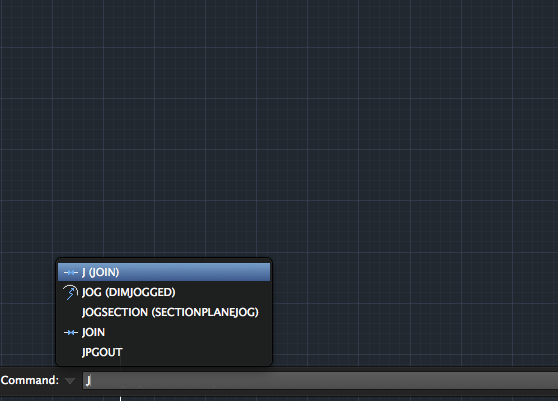
- In the command box type J for Join.
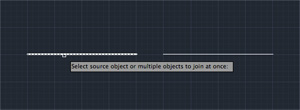
- Select source object or multiple objects to join at once then press enter.

- Objects to join and press enter.
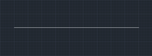
- Lines will now join to form complete lines.
-
To join multiple polylines, use the Pedit command
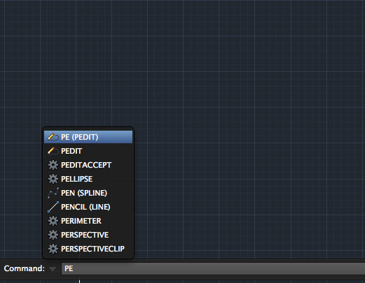
- In the command box type PE (pedit) for polyline edit.
- Press M to Select multiple lines, polylines.

- Select each line (object) as prompted one by one. Once selected they will appear dashed.

- Once you have selected all the lines press Enter you will get a set of options drop down and in the command line.
- Select the Join command to join lines / polylines together.
6. Optimizing Your AutoCAD File for Laser Cutting
-
Removing Duplicate Lines with Overkill: Use the Overkill command to remove duplicate lines or unnecessary points. This reduces the risk of multiple cuts on the same line, preventing material damage and ensuring efficiency.

-
Checking for Overlapping Objects: The Overkill tool also helps combine overlapping or co-linear objects, minimizing the complexity of your drawing and optimizing it for laser cutting.
7. Tips for Efficient Laser Cutting
-
Template Sizes: Choose templates that match the scale of your drawings to avoid excess material. For smaller components, use templates around 1000mm x 500mm rather than large ones. This prevents warping during the cutting process.
-
Multiple Drawings on One File: If working with multiple parts from the same material, arrange them on a single template. For different materials, use their corresponding templates to ensure correct settings.
-
Scaling Architectural Drawings: If adapting real-scale architectural drawings, use the correct scale factor (1 / drawing print scale) to ensure your design fits the reference border.
8. Optimizing Your Design for Laser Engraving
-
Vector vs. Raster Engraving: Keep in mind that raster engraving requires a solid fill (usually black) and is best when components are arranged closely in horizontal rows. Ensure components requiring raster engraving are set to Solid Hatch Fill in black (RGB: 0, 0, 0).
-
Depth and Appearance for Raster Engraving: We recommend a 0.25mm depth for most materials. For deeper engravings (up to 2mm), ensure to use slow speeds, as heat buildup can cause scorching and material warping.
9. Best Practices for Laser Cutting and Engraving
-
Minimum Cut Widths:
As a general rule, cut widths should not be smaller than the material thickness to ensure structural integrity and avoid fragile components. -
Handling Small Details: Small details can be fragile and may cause the material to warp. Ensure that any detail narrower than 1mm is carefully checked before cutting.
-
Efficient Arrangement: Arrange your components efficiently on the template, minimizing waste and ensuring that the laser cutting process is as efficient as possible.
You may be interested in AutoCAD Drawing Guidelines


